
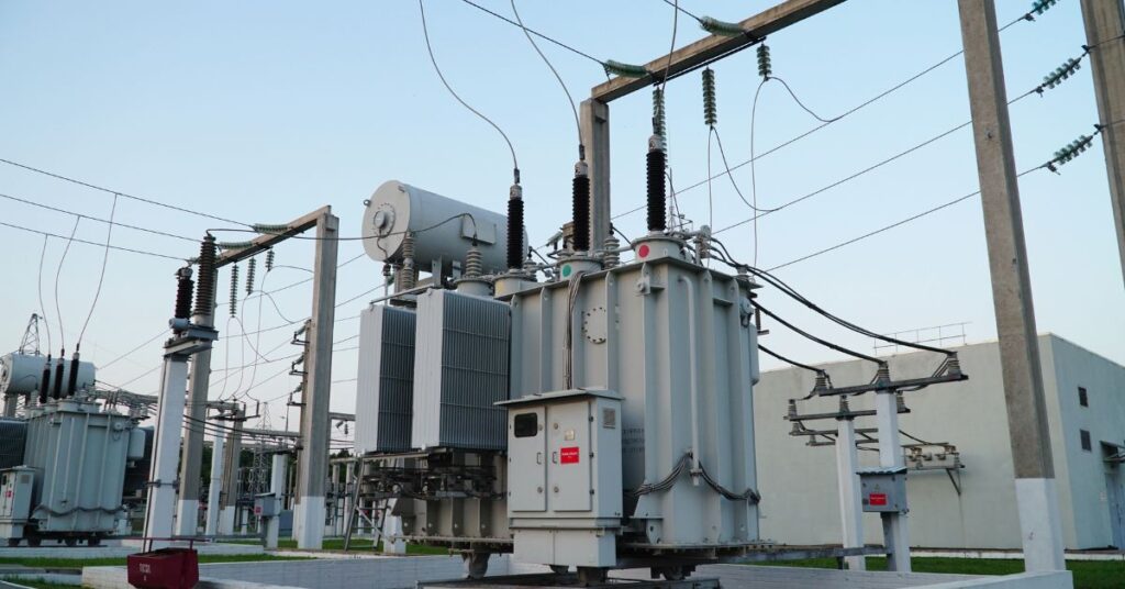
Distribution Transformer
A distribution transformer steps down medium voltage to levels your motors, lights, and equipment can actually use safely.
You’d be surprised how many electricians mix these up with power transformers. I’ve spent 50 years watching these gray boxes do the heavy lifting at paper mills in Wisconsin, refineries in Texas, and chemical plants along the Gulf Coast. They’re everywhere, and when they fail, everything stops.
Let me walk you through what really matters about distribution transformers, the stuff you won’t find in textbooks.
Table of Contents
What Exactly Is a Distribution Transformer?
Think of a distribution transformer as the final voltage step before electricity reaches your panel.
Utility power travels at 69kV, 138kV, or higher. That’s way too dangerous for a factory floor. A distribution transformer takes that medium voltage (typically 4kV to 35kV) and converts it to usable levels like 480V, 240V, or 120V depending on your load.
Here’s the simple version:
- Primary side connects to utility medium voltage
- Secondary side feeds your electrical panel
- Magnetic core transfers energy between windings
- Oil or dry-type insulation keeps things cool
I’ve seen distribution transformers rated from 10kVA serving a small pump house all the way up to 5000kVA feeding an entire manufacturing facility. Size depends on your connected load plus room for growth.
The turns ratio determines voltage change. More secondary turns than primary? Voltage goes up. Fewer secondary turns? Voltage comes down. For distribution transformers, we’re always stepping down.
How Does a Distribution Transformer Actually Work?
Pretty straightforward once you strip away the fancy engineering talk.
AC current flows into the primary winding. This creates a changing magnetic field in the iron core. That magnetic field cuts through the secondary winding and induces voltage there. No direct electrical connection between windings—just magnetic coupling.
The Core Principle
The laminated steel core is where the magic happens. Thin sheets of silicon steel stacked together reduce eddy current losses. I’ve cut open failed units and seen cores turned to rust from moisture—total waste of a $40,000 transformer.
Voltage ratio follows turns ratio:
- V_primary / V_secondary = N_primary / N_secondary
A 13.8kV to 480V distribution transformer has roughly 29:1 turns ratio.
Cooling Methods That Actually Matter
- ONAN (Oil Natural Air Natural): Most common. Oil circulates by convection, heat dissipates through tank walls. Works great up to about 2500kVA in moderate climates.
- ONAF (Oil Natural Air Forced): Add fans when ambient temps climb. Common in Arizona, Texas summer conditions.
- Dry-Type: No oil. Uses air and epoxy insulation. Required indoors where fire codes prohibit oil. I’ve installed dozens in high-rise mechanical rooms.
From what I’ve seen, ONAN distribution transformers handle 90% of outdoor industrial applications in the USA.
5 Real-World Distribution Transformer Applications in USA Industries
Let me share actual situations from my career. These aren’t textbook examples.
Example 1: Louisiana Chemical Plant
A chlor-alkali facility outside Baton Rouge runs three 2500kVA distribution transformers. Primary voltage 13.8kV, secondary 4160V for big motor loads, with smaller units stepping down further to 480V.
During a summer heat wave, one unit tripped on thermal overload. The root cause? Cooling fans failed six months earlier. Nobody noticed until ambient temps hit 105°F. Plant lost $200,000 in production before we got a rental unit trucked in from Houston.
Lesson: Check your cooling systems before summer hits.
Example 2: Ohio Automotive Stamping Plant
This facility near Toledo uses pad-mounted DT feeding 480V press lines. They upgraded from 1500kVA to 2000kVA units after adding a new transfer press.
The original DTs were running at 95% capacity. VFD harmonics pushed them over the edge. New units included K-factor ratings for harmonic loads. Problem solved.
Example 3: California Data Center
A Silicon Valley data center requires extreme reliability. They installed redundant 2000kVA dry-type DT in N+1 configuration. If one fails, the other carries full load while maintenance happens.
Fire codes demanded dry-type because these transformers sit inside the building. Oil-filled units would’ve required expensive vault construction.
Example 4: Texas Wind Farm Collection System
Wind turbines generate at 690V. Pad-mounted DTs at each turbine step up to 34.5kV for the collection system. Then substation transformers boost to transmission voltage.
I consulted on a project near Sweetwater where lightning kept killing DT bushings. Added surge arresters and improved grounding. Failures dropped 80% the next storm season.
Example 5: Michigan Food Processing Facility
A frozen pizza plant needed to add refrigeration compressors. Instead of running new 13.8kV feeders, they added a 1000kVA DT closer to the new load. Saved $150,000 in cable and conduit costs.
Smart move. Always consider transformer placement to minimize secondary cable runs.
Common Distribution Transformer Failures I’ve Witnessed
After five decades, certain failures repeat themselves. Here’s what actually kills these units.
Moisture Contamination
Water is the number one enemy. It gets in through bad gaskets, cracked bushings, or failed breathers. Once moisture contaminates the oil, insulation strength drops. I’ve measured brand new oil at 35kV dielectric strength. Wet oil? Sometimes under 15kV. That’s a failure waiting to happen.
Southern states with high humidity see this constantly. Check your silica gel breathers—pink means saturated.
Overloading Beyond Nameplate
DTs have thermal limits. Push a 1000kVA unit to 1200kVA continuously? The winding insulation degrades rapidly. Operating temperature rises 8-12°C per 10% overload.
I’ve seen windings turn brittle and crack from chronic overloading. Paper insulation that should last 30 years fails in 10.
Lightning and Switching Surges
Surge arresters exist for a reason. Skip them to save $500? You’ll spend $50,000 replacing a fried DT.
Florida and Gulf Coast installations need oversized arresters. I spec one voltage class higher than minimum for those regions.
Harmonic Overheating
VFDs, LED lighting, and computer loads create harmonic currents. These cause extra heating in DT windings and cores. Standard units aren’t designed for heavy harmonic content.
K-rated transformers handle this. K-4 for moderate harmonics, K-13 for heavy VFD loads. I’ve retrofitted dozens of facilities after standard DT failed prematurely.
Troubleshooting Distribution Transformers: My Field-Tested Approach
When a distribution transformer acts up, follow this sequence. Don’t skip steps.
Step 1: Visual Inspection
Look before you touch anything.
- Oil leaks around bushings, valves, or welds
- Bulging tank (internal pressure from fault gases)
- Burnt paint or discoloration (overheating evidence)
- Cracked bushings or damaged arresters
- Rust, especially around gaskets
I’ve caught problems just by walking around the unit slowly. One time spotted a bullet hole in a tank at a rural substation—vandalism caused the eventual failure.
Step 2: Oil Analysis
For oil-filled DTs, this test tells you everything.
Pull a sample and send it to a lab. They’ll check:
- Dielectric strength (should exceed 25kV)
- Moisture content (under 20 ppm for healthy oil)
- Dissolved gas analysis (DGA) for internal faults
- Acidity level (indicates oil degradation)
High hydrogen suggests partial discharge. High acetylene means arcing. Either one requires investigation.
Step 3: Electrical Testing
When you can safely de-energize:
- Turns ratio test: Should match nameplate within 0.5%
- Winding resistance: Compare phase-to-phase, should balance within 2%
- Insulation resistance (Megger): Minimum 1 megohm per kV rating plus 1000 megohms
- Power factor test: Indicates insulation condition
Unbalanced winding resistance points to loose connections or damaged conductors. I’ve found broken strand issues this way before they caused failures.
Step 4: Thermal Imaging
Infrared scanning under load reveals hot spots.
Loose connections show up 20-50°C hotter than surrounding areas. Internal problems sometimes show as tank hot spots. I make thermal scans part of every annual maintenance routine.
Safety Rules for Distribution Transformer Work
Don’t take shortcuts here. I’ve attended two funerals for electricians who got careless around transformers.
Key safety requirements:
- Always verify zero energy with tested equipment
- Ground all phases before touching conductors
- Treat every transformer as energized until proven dead
- Wear appropriate PPE including arc flash protection
- Follow NFPA 70E distance requirements
- Never work alone on energized equipment
Distribution transformers store energy even when disconnected. Capacitance between windings can hold dangerous charges. I always short windings to ground before touching terminals.
Oil-filled units present fire risk. Keep extinguishers rated for electrical and oil fires nearby. Some facilities require fire suppression systems near large DT.
Practical Tips and Best Practices for USA Installations
These come from real job sites, not engineering textbooks.
Sizing correctly:
- Calculate connected load plus 25% growth margin
- Account for motor starting inrush (6-8x running current)
- Consider harmonic loads requiring K-factor rating
- Don’t forget power factor correction impacts
Installation location matters:
- Pad-mounted units need level concrete pads with proper drainage
- Maintain clearances per NEC Article 450
- Consider flood zones—I’ve seen Gulf Coast units destroyed by storm surge
- Provide adequate ventilation for heat dissipation
Maintenance schedule:
- Monthly visual inspections
- Annual oil sampling for units over 500kVA
- Thermal imaging during peak load periods
- Tighten connections every 3 years
- Replace silica gel breathers when saturated
Spare transformer strategy:
- Critical facilities should stock spares or have rental agreements
- Match voltage, kVA, and impedance for parallel operation
- Document nameplate data for emergency ordering
From my experience, facilities that follow these practices see distribution transformer life spans of 30-40 years. Those that skip maintenance? Lucky to get 15 years.
Distribution Transformer Comparison Tables
Table 1: Oil-Filled vs Dry-Type Distribution Trans.
| Cooling Medium | Mineral oil | Air/epoxy |
| Fire Risk | Higher | Lower |
| Indoor Use | Requires vault | Standard installation |
| Cost (same kVA) | Lower | 30-50% higher |
| Efficiency | Slightly higher | Slightly lower |
| Maintenance | Oil testing required | Less intensive |
| Noise Level | Quieter | Louder |
| Typical Life | 30-40 years | 25-30 years |
Table 2: Common Distribution Trans. Sizes in USA Industrial Settings
| 75 | 4160V | 480V | Small pump stations |
| 150 | 13.8kV | 208Y/120V | Commercial buildings |
| 500 | 13.8kV | 480Y/277V | Medium industrial |
| 1000 | 13.8kV | 480Y/277V | Manufacturing plants |
| 2000 | 34.5kV | 4160V | Large industrial |
| 2500 | 34.5kV | 480Y/277V | Heavy industrial |
Table 3: Distribution Trans. Failure Causes and Prevention
| Overloading | 35% | High temp, humming | Proper sizing, monitoring |
| Moisture | 25% | Low dielectric | Breather maintenance |
| Lightning | 20% | Sudden failure | Surge arresters |
| Harmonics | 12% | Overheating | K-rated transformers |
| Age/Wear | 8% | Oil degradation | Scheduled replacement |
Table 4: Insulation Resistance Guidelines for Distribution Trans.
| 5kV and below | 5 megohms | 50 megohms | 500+ megohms |
| 5-15kV | 15 megohms | 150 megohms | 1000+ megohms |
| 15-25kV | 25 megohms | 250 megohms | 2500+ megohms |
| 25-35kV | 35 megohms | 350 megohms | 5000+ megohms |
Conclusion: Trust Your Distribution Transformer, But Verify
A distribution trans. does its job quietly for decades when properly selected and maintained. I’ve seen units from the 1960s still running strong because someone cared enough to check the oil and tighten connections.
The key takeaways from my 50 years in this business:
- Size for future growth, not just current load
- Respect harmonic loads with proper K-factor ratings
- Test oil annually on any unit you can’t afford to lose
- Never skip surge protection in lightning-prone areas
- Train your people on proper lockout/tagout procedures
Frequently Asked Questions About Distribution Transformers
1: What is the difference between a power transformer and a distribution transformer?
Power transformers operate at transmission voltages (69kV and above) and handle bulk power transfer between substations. Distribution transformers work at medium voltage (4kV-35kV) and deliver power directly to end users. Power transformers are larger, more efficient at full load, and located in substations. Distribution transformers are smaller, optimized for varying loads, and installed near customers on poles, pads, or inside buildings. From what I’ve seen, most industrial facilities use distribution class equipment unless they have their own substation.
2: How long does a distribution transformer last?
A well-maintained distribution trans typically lasts 30-40 years. Oil-filled units with regular testing and maintenance often exceed this lifespan. Dry-type units average 25-30 years. Factors reducing lifespan include chronic overloading, moisture contamination, harmonic loads, and inadequate cooling. I’ve personally seen units from the 1950s still operating in rural Ohio because someone maintained them properly. The key is consistent oil testing and never running above nameplate rating for extended periods.
3: What causes a distribution transformer to fail?
The top causes are overloading (35% of failures), moisture contamination (25%), lightning and surge damage (20%), harmonic overheating (12%), and age-related wear (8%). Most failures are preventable through proper sizing, surge protection, regular oil testing, and the use of K-rated transformers for harmonic loads. Chronic overloading damages insulation faster than anything else I’ve witnessed in the field. One paper mill in Wisconsin killed three distribution trans. in two years before finally upsizing its units.
4: What size distribution transformer do I need?
Calculate your connected load in kVA, add 25% for future growth, and account for motor starting inrush currents (typically 6-8 times running current). For facilities with VFDs, consider K-factor ratings for harmonic loads. A 480V facility with 800kVA connected load and motors should use a distribution trans. rated at least 1000kVA. Always consult load studies and growth projections before final sizing. Undersizing leads to overheating, reduced lifespan, and premature failure. I’ve seen too many facilities cut corners on sizing and end up paying double later.
5: How do you test a distribution transformer?
Key tests include turns ratio testing (should match nameplate within 0.5%), winding resistance measurement (phases should balance within 2%), insulation resistance using a megger (minimum 1 megohm per kV rating plus 1000 megohms), and power factor testing for insulation condition. For oil-filled distribution trans., dissolved gas analysis reveals internal faults before they become catastrophic. Thermal imaging under load identifies hot spots and loose connections. I run these tests annually on any unit I can’t afford to lose.
6: Can I install a distribution transformer indoors?
Yes, but fire codes typically require dry-type transformers for indoor installation without special provisions. Oil-filled distribution trans. require expensive vault construction with fire suppression systems, fire-rated walls, and containment for oil spills. Dry-type units with VPI (vacuum-pressure impregnated) or cast-coil construction are standard for indoor applications. Ensure adequate ventilation for heat dissipation and maintain NEC Article 450 clearances. I’ve installed dozens of dry-type units in high-rise mechanical rooms where oil wasn’t an option.
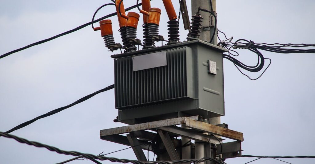
7: What is a pad-mounted distribution transformer?
A pad-mounted distribution trans. sits on a concrete pad at ground level instead of on a utility pole. These units feature locked compartments for cables and fuses, making them safer for public areas where people walk nearby. Common installations include shopping centers, industrial parks, residential subdivisions, and commercial buildings. Ratings typically range from 75kVA to 5000kVA. Dead-front designs eliminate exposed live parts, reducing arc flash hazard. You’ll see green or gray boxes throughout any commercial development.
8: How often should distribution transformer oil be tested?
Annual oil testing is recommended for distribution trans. over 500kVA or those critical to operations. Test parameters include dielectric strength (minimum 25kV), moisture content (under 20 ppm), dissolved gas analysis, and acidity level. High hydrogen levels indicate partial discharge within the unit. Elevated acetylene levels suggest active arcing and require immediate attention. Moisture above 20 ppm degrades insulation rapidly and must be addressed. Regular testing catches problems months or years before they cause expensive failures and downtime.
9: What is a K-rated distribution transformer?
K-rated distribution trans. are designed to handle harmonic currents from non-linear loads like VFDs, computers, LED lighting, and rectifiers. Standard transformers overheat when harmonics are present because those currents cause additional losses in windings and cores. K-4 handles moderate harmonic content found in most commercial buildings. K-13 is appropriate for heavy VFD applications in manufacturing. K-20 suits extreme cases with very high harmonic distortion. The K-factor indicates the amount of additional harmonic heating the transformer can withstand without insulation damage.
10: Why does my distribution transformer hum loudly?
Loud humming typically indicates loose core laminations, DC offset from half-wave rectifier loads, or over-excitation from high incoming voltage. Magnetostriction (core vibration from magnetic forces) causes normal hum in all transformers, but increased noise signals developing problems. Check for loose mounting bolts first, as vibration can loosen hardware over time. If harmonics are present from VFDs or other nonlinear loads, the distribution trans. may require a K-factor rating. A sudden increase in noise warrants immediate investigation and possible de-energization for internal inspection.
11: What voltage does a distribution transformer output?
Common secondary voltages in USA industrial applications include 480Y/277V (most industrial facilities), 208Y/120V (commercial and light industrial), 240/120V (single-phase residential and small commercial), and 4160V (large motor loads in heavy industry). The specific voltage depends on your electrical system design and load requirements. Primary voltages for distribution trans. typically range from 4.16kV to 34.5kV depending on utility supply. Three-phase wye connections provide both line-to-line and line-to-neutral voltages for flexibility.
12: How do you ground a distribution transformer?
Ground the distribution transformer tank to the grounding electrode system using properly sized conductors. For wye-connected secondaries, bond the neutral point to ground at the transformer or at the first disconnect per NEC requirements. Follow NEC Article 250 for grounding electrode conductor sizing per Table 250.66 based on secondary conductor size. Separately derived systems require specific grounding configurations, including a bonding jumper and a grounding electrode conductor. Poor grounding causes voltage issues, equipment damage, and serious safety hazards I’ve seen repeatedly throughout my career.
13: What causes a distribution transformer to overheat?
Overheating results from overloading beyond nameplate rating, harmonic currents in standard (non-K-rated) transformers, blocked ventilation or failed cooling fans, high ambient temperatures exceeding design basis, and internal faults developing between turns or layers. Monitor the top oil temperature and the winding hot-spot temperature if gauges are installed. Temperatures above 105°C for oil-filled units or 180°C for dry-type units indicate serious problems requiring immediate load reduction or a complete shutdown. A distribution transformer running hot is a distribution transformer dying slowly.
14: Can I run two distribution transformers in parallel?
Yes, but distribution transformers must match closely in voltage ratio, impedance (within 7.5% of each other), and polarity for successful parallel operation. Phase rotation must be exactly aligned for three-phase units, or severe circulating currents result. Mismatched impedances cause unequal load sharing, with lower-impedance units carrying more than their share of current. Voltage ratio differences create circulating currents that waste energy and cause heating. I always recommend identical transformers from the same manufacturer purchased together for parallel operation.
15: What maintenance does a distribution transformer need?
Monthly visual inspections should check for oil leaks, physical damage, rust, and abnormal conditions like bulging tanks. Annual maintenance includes oil sampling and testing, thermal imaging under load, and checking connection tightness. Every 3-5 years, perform comprehensive electrical testing, including turns ratio, winding resistance, insulation resistance, and power factor tests. Replace silica gel breathers when color indicates saturation (typically pink or white). Keep vegetation cleared at least 10 feet around pad-mounted units. Document everything for trending analysis over time.
16: What is the difference between ONAN and ONAF cooling?
ONAN means Oil Natural Air Natural, where oil circulates by convection and heat dissipates naturally through the tank and radiators. ONAF stands for Oil Natural Air Forced, where fans blow air across radiators to improve cooling capacity. ONAN distribution trans. work great in moderate climates up to about 2500kVA. ONAF allows the same-sized unit to handle 25-33% more load by adding fans. I spec ONAF for Texas, Arizona, and other hot climates where summer ambient temperatures regularly exceed 100°F.
17: How do I know if my distribution transformer is overloaded?
Signs of overloading include high oil or winding temperature readings, transformer humming louder than normal, tripping of thermal overload devices, oil darkening faster than expected, and dissolved gas analysis showing thermal degradation. Measure actual load current with a clamp meter and compare to the nameplate rating. Loading above 100% continuously degrades insulation life. Above 120% causes rapid deterioration. Many facilities don’t realize their distribution trans. is overloaded until something fails during peak summer demand.
18: What is dissolved gas analysis, and why does it matter?
Dissolved gas analysis (DGA) tests oil samples for gases produced by internal faults in distribution transf.. Different fault types produce different gases. Hydrogen indicates partial discharge or corona. Methane and ethane suggest low-temperature thermal faults. Ethylene indicates higher temperature faults. Acetylene means arcing has occurred, which is serious. Carbon monoxide and carbon dioxide indicate paper insulation degradation. DGA catches problems early before they cause catastrophic failures. It’s the best diagnostic tool we have for oil-filled transformers.
19: Can a distribution transformer explode?
Yes, distribution trans. can explode when internal arcing faults generate gases faster than pressure relief devices can vent them. Lightning strikes, internal short circuits, severe overloads, and oil contamination can trigger explosive failures. Modern units include pressure relief valves, and some have rapid-pressure-rise relays to disconnect before an explosion. I’ve seen the aftermath of transformer explosions at substations. Proper surge protection, regular maintenance, and not ignoring warning signs, such as abnormal DGA results, prevent most catastrophic failures.
20: What is tap changer on a distribution transformer?
A tap changer adjusts the distribution trans. turns ratio to compensate for voltage variations. Most distribution units have no-load tap changers (NLTC) that require de-energizing before adjustment. Taps typically provide ±2.5% or ±5% voltage adjustment in 2.5% steps. If the incoming voltage runs consistently high or low, technicians adjust the taps to bring the secondary voltage within an acceptable range. Some larger units have automatic load tap changers (LTC) that adjust while energized. I check tap positions whenever troubleshooting voltage complaints.
21: What is impedance in a distribution transformer?
Impedance represents the distribution trans. internal opposition to current flow, expressed as a percentage of rated voltage. Typical impedance for distribution class units ranges from 4% to 6%. Lower impedance means higher available fault current on the secondary requiring larger breakers. Higher impedance limits fault current but causes greater voltage drop under load. Impedance also affects motor starting voltage. When paralleling transformers, impedance values must match within 7.5% for proper load sharing between units.
22: How do I read a distribution transformer nameplate?
Key distribution trans. nameplate information includes kVA rating (continuous capacity), primary voltage and connection, secondary voltage and connection, impedance percentage, BIL (basic insulation level), cooling class (ONAN, ONAF, etc.), temperature rise rating, and weight. The serial number and manufacturing date help with warranty and maintenance records. The vector group, or angular displacement, shows the phase relationship between the primary and secondary. Tap positions indicate available voltage adjustments. I photograph every nameplate during installation for future reference.
23: Why do some distribution transformers use FR3 fluid instead of mineral oil?
FR3 is a natural ester fluid made from soybean oil that offers significant fire safety advantages over mineral oil. FR3 has a fire point above 360°C compared to mineral oil around 170°C. This makes FR3 distribution trans. safer for indoor installation and near buildings. FR3 also biodegrades if spilled, reducing environmental liability. The fluid costs more but may eliminate need for fire suppression systems. I’ve specified FR3 units for data centers and food processing plants where fire risk must be minimized.
24: What clearances are required around a distribution transformer?
NEC Article 450 specifies clearances based on voltage level and installation type. Indoor dry-type units require a minimum 12 inches of clearance for ventilation on all sides with openings. Oil-filled units need specific distances from buildings and combustible materials. Pad-mounted distribution trans. require working space for operation and maintenance. Local codes may add requirements. Fire codes specify separation distances based on oil volume. I always check both NEC and local amendments before designing transformer installations.
25: How much does a distribution transformer cost?
Distribution trans. prices vary widely based on kVA rating, voltage class, and type. Small 75 kVA pad-mounted units start at $8,000-12,000. Medium 500kVA units run $25,000-40,000. Large 2500kVA units cost $80,000-150,000 or more. Dry-type costs 30-50% more than oil-filled for equivalent ratings. K-rated units add 15-25% premium. Custom voltage combinations, special BIL ratings, and fast delivery increase costs. Installation, concrete pads, and connections add substantially to total project cost. Always get multiple quotes and check lead times which can exceed 20 weeks.