
Type 1 vs Type 2 Surge Protection Device selection decides whether PLCs, VFDs, and control cards survive a lightning surge or fail instantly in real plants.
If you’ve ever replaced circuit boards after a storm, this will make sense in a hurry. We’ll walk through it as we do on real jobs - straight talk, minimal theory fluff.
- Concept and Standards for Type 1 vs Type 2 Surge Protection
- How Each SPD Stage Works
- Detailed Comparison of Type 1 vs Type 2 Surge Protection Device
- Why Type 1 vs Type 2 Surge Protection Device Matters
- 5. Common Installation Mistakes Engineers Still Make
- 6. Troubleshooting and Safety Checks
- 7. Practical Tips and Best Practices from Field Experience
- 8. Hidden Field Lessons and Overlooked Risks
- 9. Real‑World Industrial Scenarios
- 10. Quick‑Reference Selection Table
- 11. Summary
- 12. FAQ Section
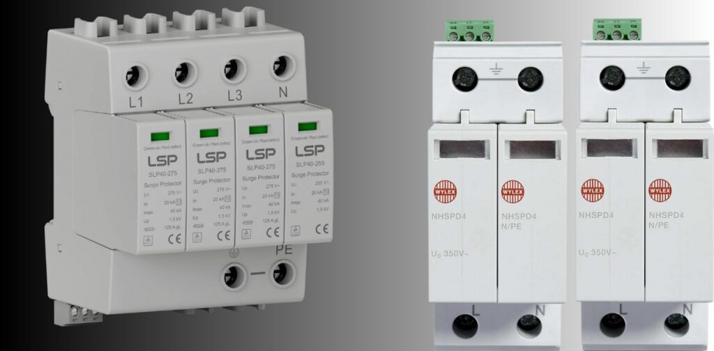
Fig-1: Type 1 vs Type 2 Surge Protection Device installation example
Concept and Standards for Type 1 vs Type 2 Surge Protection
A Surge Protection Device (SPD) acts like a pressure‑relief valve for voltage.
Whenever a transient, lightning, utility switching, AC motor starts, tries to spike past normal limits, the SPD shunts that burst to ground within microseconds.
Every unit sold in the U.S. must comply with UL 1449 4th Edition, and worldwide with IEC 61643‑11.
Let’s decode the ratings that matter most.
| Symbol | Name | Function | Typical Range |
|---|---|---|---|
| Uc | Continuous operating voltage | Max RMS voltage the SPD tolerates continuously | 275 – 550 V AC |
| Up | Voltage protection level | Clamp voltage delivered to equipment during surge | 0.8 – 2.0 kV |
| In | Nominal discharge current (8/20 µs) | Repetitive surge rating | 5 – 20 kA |
| Iimp | Impulse current (10/350 µs) | Lightning‑stroke test current | 5 – 50 kA |
Match Uc ≥ 1.1 × system voltage; keep Up below your gear’s BIL (basic impulse level).
How Each SPD Stage Works
Let’s pull them apart the way we would on a bench.
1. Type 1 SPD - Service Entrance Front Line
Purpose
Handles direct or indirect lightning surges from the utility feed before the main breaker.
Internal Design
Usually a hybrid: spark gap or gas‑discharge tube (GDT) in series with an MOV array.
When voltage exceeds about 2–3 kV, the spark gap fires, creating a plasma path that diverts 10/350 µs lightning currents to ground.
The MOVs then clean up the tail of the waveform, clamping within ~1.5 kV on a 480 V system.
Connection Method
Mounted on the supply side of the service disconnect or in a meter collar.
Conductors are thick (#6 AWG Cu minimum) and under 18 inches.
As Per NEC 285.25, Type 1 SPDs may connect without a dedicated breaker, since they’re rated for line‑side duty.
Waveform Handling
Designed for 10/350 µs lightning pulses, 25–50 kA per mode, < 100 ns response.
Real Example
At a Florida cogeneration plant, a Type 1 SPD on the 480 V service absorbed ≈ 35 kA from nearby lightning. Plant kept running; SPD indicator turned amber , but everything behind it was fine.
2. Type 2 SPD – Downstream Load‑Side Protection
Purpose
Stops residual energy that gets past the front line and kills sensitive electronics (VFDs, PLCs, HMIs). Also handles surges caused internally by motors and contactors.
Internal Design
Primarily MOV‑based, sometimes with silicon avalanche diodes (SADs) for ultra‑fast response.
Above ≈ 1.5 × system voltage, the MOV impedance drops from mega‑ohms to milliohms in ~25 ns, diverting the spike.
Thermal disconnects open if MOVs overheat from cumulative stress.
Installation
Always on the load side of the main breaker—typically on a dedicated two‑pole 20–30 A breaker or directly to panel bus.
Mount closest to the main lugs to minimize lead inductance.
Waveform Handling
Rated for 8/20 µs ring wave, 5–20 kA per mode, Up ≈ 0.8–1.2 kV, response < 25 ns.
Perfect for filtering the finer electrical noise that never trips fuses but ages electronics.
Real Example
At a California EV‑charging lot, rectifier switching created 3 kV bursts on feeders. Panel‑mounted Type 2 SPDs captured every event (18 logged in a month) with no damage to $12 000 rectifier modules.
3.Type 1 + Type 2 Coordination
Energy coordination means one stage handles the bulk, the next stage handles what’s left.
Spacing one distribution level between Type 1 and Type 2 SPDs lets the naturally existing line impedance divide the energy.
Front‑end absorbs 10/350 µs lightning currents; downstream unit soaks the 8/20 µs aftershock. Proper coordination between Type 1 vs Type 2 Surge Protection device units ensures energy is divided safely across stages.
Detailed Comparison of Type 1 vs Type 2 Surge Protection Device
| Parameter | Type 1 SPD | Type 2 SPD |
|---|---|---|
| Test waveform | 10/350 µs (lightning stroke) | 8/20 µs (switching pulse) |
| Core components | Spark gap + MOV hybrid | MOV / SAD |
| Energy capacity | Very high | Medium |
| Typical Iimp | 25 – 50 kA per mode | 5 – 20 kA per mode |
| Mount position | Supply side of main disconnect | Load side (main or subpanel) |
| NEC reference | 285.25 (Line side approved) | 285.24 (Load side only) |
| Response time | < 100 ns | < 25 ns |
| Maintenance | Low (check indicator) | Moderate (heat aging check) |
Why Type 1 vs Type 2 Surge Protection Device Matters
Understanding Type 1 vs Type 2 Surge Protection Device selection matters because modern facilities face constant transients. Even in clean U.S. power grids, micro‑surges are constant. IEEE data shows that the average facility receives hundreds to a few thousand transient hits per year. Most come from inside contactors, compressors, VFDs, not just lightning.
1. Industrial Examples of Surge Stress
| Facility Type | Typical Surge Source | SPD Stage Needed | Result of Proper Use |
|---|---|---|---|
| Power plants | Generator breaker swings, switchyard lightning | Type 1 + Type 2 | Protects turbine PLC and relay racks |
| Oil & gas field MCCs | Induction from 480 V motors | Type 2 in each MCC | Prevents I/O card and RTU trips |
| EV charging stations | Utility switching, rectifier backfeed | Type 1 + Type 2 | Prevents charger reset and rectifier damage |
| Food factories | Conveyor start/stop cycles | Type 2 | Extends PLC I/O life |
| Solar farms | PV arc faults and inverter kickback | DC SPD (Type 2 DC) + AC Type 1 | Keeps MPPT controllers alive |
Without those SPDs, one impulse can cook a $2 000 VFD board or freeze a 400‑HP compressor start sequence.
Honestly, I’ve seen that happen too many times to count.
2. Why Two Stages Are Better Than One
Think of surge protection like fire suppression: Type 1 is the exterior firewall; Type 2 is the sprinkler system inside.
The combination provides redundancy and meets NEC 285 recommendations and many insurers’ electrical‑loss standards.
- Type 1 absorbs the heavy 10/350 µs front from lightning or utility faults.
- Type 2 kills leftover 8/20 µs waves and endemic switching noise.
The two complement each other, miss either one and you’ve got a hole in your defense chain.
5. Common Installation Mistakes Engineers Still Make
After 20+ years of seeing every panel configuration imaginable, here’s the hard‑earned list.
1. Wiring and Layout Errors
- Long leads: Every extra inch adds ≈ 25 V of let‑through voltage. Keep conductors under 10 inches, twist L‑N leads together.
- Poor bonding: Ground resistance > 5 Ω makes even $500 SPDs nearly useless.
- Wrong type location: Type 2 device on utility line side = code violation under NEC 285.24.
- Unprotected neutral: Skipping N‑G path invites differential surges through sensitive equipment.
- No breaker or fuse coordination: Type 2 SPDs without OCPD may fail short on aging MOVs.
| Mistake | Typical Effect | Corrective Action |
|---|---|---|
| Lead too long | Higher let‑through | Keep < 10 inches, twist leads |
| Ground > 5 Ω | Reduced clamping efficiency | Improve ground electrode system |
| Type 2 on line side | Code violation | Use Type 1 only on line side |
| Missing neutral bond | Floating voltages on electronics | Bond as per NEC 250 Rules |
| No breaker isolation | Fire risk on MOV failure | Use dedicated 2‑pole breaker or fuses |
2. Specification Mistakes
- Sizing too small (5 kA) for 480 V industrial service is like using a garden hose for firefighting. Go at least 20–40 kA per mode.
- Confusing UL Type rating with device design family, Type 1/2 per UL 1449 does not equal Type I/II by IEC; check label scope.
- Ignoring environment—ambient > 40 °C ages MOVs twice as fast.
6. Troubleshooting and Safety Checks
You’d be surprised how many panels I open where the SPD LED is dark, and nobody knows.
These quick inspections save thousands.
1. Routine Inspection Checklist
| Check Item | Frequency | Method | Expected Result |
|---|---|---|---|
| Indicator LED | Monthly | Visual | Green = Active / Red = Replace |
| Ground bond resistance | Annually | Earth tester | < 5 Ω |
| Thermal condition of MOV block | Semi‑annual | IR gun | Below 60 °C surface |
| Surge counter (if fitted) | After storms | Record | Log event number |
| Connection torque | After seasonal cycle | Torque wrench | Per label spec |
Pro tips
- Label panel with install date; replace unit after 5–10 years or post‑major event.
- For SPD without a counter, note visible LED changes in the maintenance book.
- Always test de‑energized. If you must observe indicators live, keep one hand in your pocket and stand on a dry rubber mat.
2. Typical Field Symptoms and Fixes
| Symptom | Root Cause | Recommended Action |
|---|---|---|
| Repeated breaker trip on SPD branch | Internal MOV short or ground fault | Replace module; verify OCPD rating |
| Equipment still damaged after install | Ground loop or wrong SPD type | Bond properly; add coordinate Type 1 ahead of Type 2 |
| Indicator light off | MOV open circuit or unit dead | De‑energize and replace |
| SPD runs hot | Underrated unit or loose lug | Torque check; upgrade higher current rating |
| Communication PLC noise even with SPD | Surge filter on data lines missing | Add low‑voltage data‑line arrestors |
3. What Is the Difference Between Type 1 and Type 2 Surge Protection?
A Type 1 SPD sits between the utility and service disconnect; it handles high‑energy events (10/350 µs lightning).
A Type 2 SPD mounts on the panel’s load side and clamps smaller 8/20 µs surges from motors or residual waves.
Install both for full coverage—from meter to equipment.
4. Do I Need Type 1 or Type 2 SPD? (Direct PAA)
Short answer: You need both if you run any microprocessor‑based hardware (VFDs, PLCs, inverters).
Only low‑risk rural circuits with underground feed might survive on Type 2 alone, but that’s a gamble.
Modern codes and insurers all endorse the dual‑stage method.
7. Practical Tips and Best Practices from Field Experience
Fifty years in plants and MCC rooms teach you patterns the books never cover.
Follow these, and most SPD projects simply work.
1. Installation Tips
- Shortest lead wins. Keep overall wiring length < 10 inches; use flat braided jumpers if panel space is tight.
- Twist hot and neutral together. Twisting reduces loop area → reduces inductance → better clamp voltage.
- One ground bond only at the service main. Split neutral/ground in subpanels per NEC 250 to avoid parallel paths.
- Torque everything. MOV terminals loosen with heat; use the manufacturer’s torque chart.
- Use Labeling. Tag each SPD with install date, circuit ID, and nominal discharge rating.
2. Design Coordination Tips
| Design Step | Key Detail | Benefit |
|---|---|---|
| Stage separation | One distribution level (min 20 ft of conductor) between Type 1 and Type 2 | Natural impedance for energy coordination |
| Correct In/Iimp selection | Match to service kVA and exposure level | Prevents underrating and over‑stress |
| SPD counter monitoring | < 50 events per year typical | Identify utility switching issues |
| Ground system audit | Measure every 6 – 12 months | Maintains < 5 Ω resistance for reliable clamping |
When adding new solar or EV gear, re‑calculate SPD current ratings; those loads create new paths for surges.
8. Hidden Field Lessons and Overlooked Risks
1. Ground Loops and Potential Rise
Separate building grounds (automation room vs main panel) act at different potentials during a strike.
The voltage difference travels through signal cables and ruins IO cards faster than a transient.
Solution: bond all subsystem grounds to one reference bus with #4 Cu minimum.
2. MOV Degradation Over Time
A 30 kA strike consumes ~25 % of a 50 kA‑rated unit’s capacity. Check the LED even if it’s still green.
MOVs age by energy exposure, not by calendar years.
Simplified formula:
Remaining Life ≈ 1 − (Wevents / Wrated)
where W = ½ × I × V × t.
A 30 kA strike consumes approximately 25% of a 50 kA‑rated unit’s capacity. Check the LED even if it’s still green.
3. Don’t Oversize Blindly
Oversizing a Type 2 SPD to 80 kA for a small 240 V panel isn’t longevity—it’s thermal stress. MOVs carry leakage current even when idle; bigger stacks heat more in small enclosures.
4. Real SPD Counter Value Meaning
Counters only record threshold crossings, not energy magnitude. If you log frequent small hits, suspect utility switching or harmonic distortion.
9. Real‑World Industrial Scenarios
1. Power Plant – Gas Turbine Control System
Lightning hit the stack structure. Type 1 SPD at the service transformer absorbed 40 kA; Type 2 SPDs on 480 V MCCs kept Woodward governors steady. No unplanned trip.
2. Fertilizer Plant – MCC Sections
Regular VFD failures every wet season. Installed Type 2 SPDs (20 kA In) on each feeder. Zero drives lost in three monsoons running.
3. EV Charging Hub
Utility switching surges and back‑fed DC faults killed two rectifiers. Dual Type 1 (36 kA) + Type 2 (12 kA) combination eliminated failures; logged seven events in year one.
4. PLC Network – Chemical Processing Unit
Intermittent PLC resets during motor starts. Added Type 2 SPDs at the 24 V control supply and separate data‑line arrestors; network uptime jumped 99.9 %.
5. Residential House in Tampa
A half-mile lightning strike took out neighboring TVs. A meter-based Type 1 plus panel‑mount Type 2 kept everything alive. Total install cost $450 , cheap insurance.
10. Quick‑Reference Selection Table
| Environment | Recommended Type | Typical Rating (Iimp / In) | Notes |
|---|---|---|---|
| Overhead utility feed, high lightning area | Type 1 + Type 2 | 50 kA / 20 kA | Standard residential Florida |
| Underground service in city | Type 2 only | 10 kA / 5 kA | Low lightning risk |
| EV charging station | Type 1 + Type 2 | 36 kA / 15 kA | Handles utility switching |
| Industrial MCC 480 V | Type 1 + Type 2 | 65 kA / 20 kA | Protects VFDs and controls |
| Solar PV farm (DC + AC) | DC SPD + Type 1 AC | 20 kA each mode | Protects inverter MPPT |
11. Summary
A Type 1 vs Type 2 Surge Protection Device setup is simply cheap insurance for modern electronics. A Type 1 SPD blocks the outside world’s spikes; a Type 2 SPD handles your own facility’s transients. Together, they build the layered defense required by NEC Article 285 and common sense.
Wire them short, bond them tight, and check LEDs monthly. Do that , and your controllers, drives, and IT gear will thank you every storm season.
If you’re unsure about panel layout or breaker coordination, call a licensed electrician—safety beats ego every time.
12. FAQ Section
What is the difference between Type 1 and Type 2 surge protection?
Type 1 handles line‑side lightning surges; Type 2 handles load‑side residuals from switching.
Do I need Type 1 or Type 2 SPD?
Both for full coverage from utility to equipment.
What is a Type 1 surge protector?
Line‑side device using spark gaps and MOVs rated 25–50 kA.
What is a Type 2 device?
Panel‑mount SPD using MOVs / SADs for 5–20 kA.
What is surge protection Type 2?
It absorbs residual 8/20 µs pulses after Type 1.
What is Type 3 SPD?
Point‑of‑use plug‑in protectors for equipment cords.
What is Type 4 SPD?
Component modules built into OEM devices.
What is the best Type 1 SPD for homes?
Eaton CHSPT1ULTRA; UL 1449 Listed 50 kA class.
Best Type 2 SPD for panels?
Square D HOM2175SB (UL Type 2, 25 kA).
Can Type 2 SPD protect against lightning?
Only indirectly; needs Type 1 ahead.
Do SPDs reduce the electric bill?
No, all they do is prevent damage.
How long do SPDs last?
About 5–10 years , depending on hits and temperature.
Do SPDs need maintenance?
Visual and torque checks only.
Can I install SPD myself?
Plug‑in ones , yes; service entrance requires a licensed electrician.
What causes SPD failure?
Repeated surge energy and heat cycling.
Why does the LED turn off but power on?
Protection stage burned open, replace module.
What is Nominal Discharge Current (In)?
Test value for repetitive 8/20 µs surges.
What is Impulse Current (Iimp)?
Lightning‑stroke test 10/350 µs.
Should data lines also have SPDs?
Yes, use RJ45 / coax arrestors.
Is surge protection mandatory in U.S. homes?
Since NEC 2020, it is required for new dwelling units.
Type 1 vs Type 2 vs Type 3 SPD: Key Differences & Comparison Guide 2026